UML SEQUENCE DIAGRAM EXPLAIN HOW TO
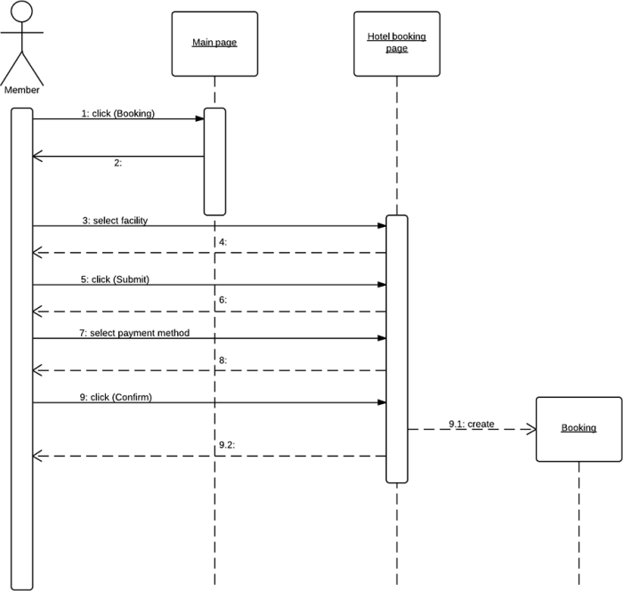
How to create a sequence diagram for a library management system So now that you know something about how sequence diagrams are put together, let’s move on to creating an example sequence diagram in the easy-to-use Gleek diagramming tool. If you want to read about more complex elements in sequence diagrams, check out this more detailed blog post: Sequence diagram with fragments: Loop, alternative, option or watch this video of a cashier example sequence diagram. Those are the basics about sequence diagrams and should be enough for you to understand our example sequence diagram. The length of the box tells you the duration of activity. A vertical box called an activation bar is placed on the lifeline to indicate that the object is processing the message or carrying out a command. When a message hits an object’s lifeline, that object can be activated. Make your own UML sequence diagram with Gleek. These represent messages passing between the objects. The interactions between objects are shown as horizontal arrows that go left or right. The objects included are shown at the top and bottom of the diagram as labeled rectangles with a lifeline descending the full length of the diagram. The sequence diagram moves from top to bottom to show the sequence of events in the system. Let’s quickly summarize the basic elements in a sequence diagram.

This can make it easier to identify potential problems and optimize how everything works. A sequence diagram helps the designer of a system visualize and understand the order in which these interactions occur.

They’re used to show how objects in a system work together over time.

Sequence diagrams are a type of Universal Modeling Language (UML) diagram.


 0 kommentar(er)
